-40%
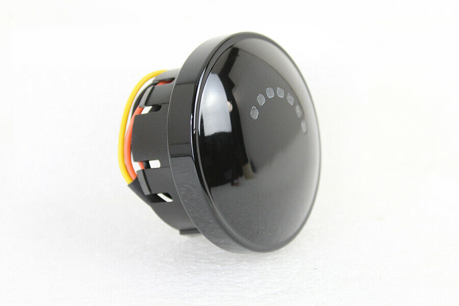
Harley Fuel Gauge Black LED 75242-08 Fits FLST FXST FLHR 08 Up V-Twin 38-0507 Y2
$ 28.5
- Description
- Size Guide
Description
Harley Fuel Gauge Black LED 75242-08 Fits FLST FXST FLHR 08 Up V-Twin 38-0507 Y2High Quality
Best Offers
Fast Shipping
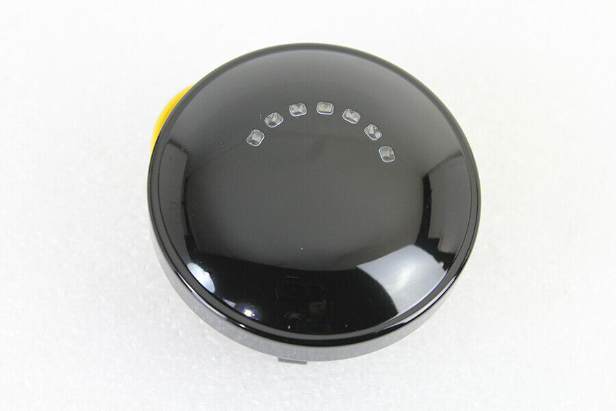
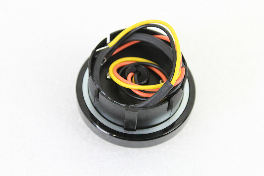
Check out this Quality V-Twin LED fuel gauge that features a black finish. Part Number 38-0507
More Information
OEM Harley Part Number: 75242-08
UOM1 - EA
ManufacturerWyatt Gatling
OriginImported
FITS Harley-Davidson
FLST 2008-UP
FXST 2008-UP
FLHR 2008-UP
FXDWG 2009-UP
LED FUEL GAUGE KIT
VT No. 38-0506, 38-0507
NOTE: This requires some wiring, NOT plug and play if you are not good at this consider having this professionally installed or maybe not purchase this !
This instruction sheet references service manual information. A service manual for your
model motorcycle is required for this installation and is available from a dealer.
REMOVAL
WARNING
Rider and passenger safety depend upon the correct installation of this kit. Use the appropriate service manual procedures. If the procedure is not within your capabilities or you
do not have the correct tools, have a dealer perform the installation. Improper installation
of this kit could result in death or serious injury.
WARNING
To prevent accidental vehicle start-up, which could cause death or serious injury, disconnect negative (-) battery cable before proceeding.
WARNING
When servicing the fuel system, do not smoke or allow open flame or sparks in the vicinity. Gasoline is extremely flammable and highly explosive, which could result in death or
serious injury.
1. Refer to the owner’s manual and follow the instructions given to remove the seat and
disconnect the negative battery cable. Retain all seat mounting hardware.
Removing the Analog Fuel Gauge
NOTE
The fuel gauge wires are routed through a tube in the fuel tank, and are secured by a clip
at the bottom of the tank and, on some models, a clamp on the frame. Open the clip and
clamp as needed, and be sure there is enough slack in the wires to be able to lift out the
gauge.
At the bottom left side of the fuel tank, bend back the flexible clip slightly to free the
fuel gauge conduit. Open the harness clamp on the frame if necessary to free the conduit.
Gently pull on the conduit to draw the Multilock connector [117] out of the tunnel.
See Figure 2. Press the pin on the socket terminal side of the connector, and pull apart
the pin and socket halves.
See Appendix B in an appropriate service manual. Use a pick (Snap-On TT600-3 or
equivalent) to remove the terminals or clip off the wires. Remove and discard the fuel
gauge.
Remove the fuel gauge by firmly grasping and carefully pulling up (do NOT twist) on
the gauge to free it from the fuel tank. Feed the conduit and three wires up through the
tube while removing the gauge. Remove and discard the fuel gauge.
Remove and discard the rubber gasket.
INSTALLATION
1. See Figure 2. Assemble the new gasket (3) to the LED fuel gauge (1) from the kit.
Install the gasket so the flat side contacts the edge of the gauge.
2. See Figure 1. Use three of the Phillips-head screws and washers from the kit to connect
the wires as follows: Fasten the Orange wire (1) ring terminal to the gauge connection
marked “12V and “O” with a screw and washer. Fasten the Black wire (2) ring terminal
to the connection marked “GND” and “BK” with a screw and washer. Fasten the Yellow/
White wire (3) ring terminal to the connection marked “Y/W” with a screw and washer.
3. While carefully lowering the fuel gauge, feed the wire harness (2) down into the drain
tube until the three short (Orange, Black, Yellow/White) wires exit the hole at the bottom
of the fuel tank. Gently pull the wires to remove slack while installing the gauge to the fuel
tank. Do not twist the gauge during installation. Hold the gauge firmly and press down
until it snaps into place.
4. Install the three wires with pin terminals (B) into the correct cavities of the 4-place pin
housing (4) from the kit. See below and Appendix B of an appropriate service manual. -
Cavity 1: Orange - Cavity 2: Yellow/White - Cavity 3: Open - Cavity 4: Black
[276565]
1 Orange wire to “12V O”
2 Black wire to “GND BK”
3 Yellow/White wire to “Y/W”
Figure 1. Wire Connections
5. At the bottom left side of the fuel tank, mate the completed pin housing to the socket
housing [117B] disconnected in Step 3 of the REMOVAL section. Feed the connector
into the tunnel, capturing the conduit in the flexible clip at the bottom of the tank and the
clamp on the frame (if so equipped)
WARNING
After installing seat, pull upward on seat to be sure it is locked in position. While
riding, a loose seat can shift causing loss of control, which could result in death or
serious injury.
6. Refer to the owner’s manual and follow the instructions given to connect the
negative (-) battery cable and install the seat.
NOTE
If the fuel gauge does not indicate the proper fuel level after installing this kit, check
the connectors, then follow the troubleshooting procedures in the service manual.
Figure 2. Service Parts: LED Fuel Gauge Kit
Table 1. Service Parts Table: LED Fuel Gauge Kit
Item Description (Quantity) Part Number
1 Fuel gauge, LED Not Sold Separately
2 Wiring harness 70008-08
3 Gasket, fuel gauge 27730-04
4 Pin housing, 4-pin 72904-01BK
5 Hardware kit (not shown) 75003-04
Items mentioned in text, but not included in kit:
A Wire conduit
B Pin terminals
Payment
BUY NOW!
We accept payment by any of the following methods:
PayPal
Please pay as soon as possible after winning an auction, as that will allow us to post your item to you sooner!
Returns
We offer FREE Lower 48 USA shipping on most orders! (large items and freight not included)
Your order will be dispatched within 1 working day of receiving payment (Monday-Friday) and you should expect to receive it according to the shippers tracking information that will be provided to you after payment is received and your item has been shipped
In the very unlikely event that your item is lost or damaged during post, then WE are responsible and will issue either a full refund or replacement.
Shipping
If you are not 100% satisfied with your purchase, you can return the product and get a full refund or exchange the product for another one, be it similar or not.
You can return a product for up to 30 days from the date you purchased it.
Any product you return must be in the same condition you received it and in the original packaging. Please keep the receipt.
High Quality
Best Offers
Fast Shipping
Check out this Quality V-Twin LED fuel gauge that features a black finish. Part Number 38-0507 More Information OEM Harley Part Number: 75242-08 UOM1 - EA ManufacturerWyatt Gatling OriginImported FITS Harley-Davidson FLST 2008-UP FXST 2008-UP FLHR 2008-UP FXDWG 2009-UP LED FUEL GAUGE KIT VT No. 38-0506, 38-0507 NOTE: This requires some wiring, NOT plug and play if you are not good at this consider having this professionally installed or maybe not purchase this ! This instruction sheet references service manual information. A service manual for your model motorcycle is required for this installation and is available from a dealer. REMOVAL WARNING Rider and passenger safety depend upon the correct installation of this kit. Use the appropriate service manual procedures. If the procedure is not within your capabilities or you do not have the correct tools, have a dealer perform the installation. Improper installation of this kit could result in death or serious injury. WARNING To prevent accidental vehicle start-up, which could cause death or serious injury, disconnect negative (-) battery cable before proceeding. WARNING When servicing the fuel system, do not smoke or allow open flame or sparks in the vicinity. Gasoline is extremely flammable and highly explosive, which could result in death or serious injury. 1. Refer to the owner’s manual and follow the instructions given to remove the seat and disconnect the negative battery cable. Retain all seat mounting hardware. Removing the Analog Fuel Gauge NOTE The fuel gauge wires are routed through a tube in the fuel tank, and are secured by a clip at the bottom of the tank and, on some models, a clamp on the frame. Open the clip and clamp as needed, and be sure there is enough slack in the wires to be able to lift out the gauge. At the bottom left side of the fuel tank, bend back the flexible clip slightly to free the fuel gauge conduit. Open the harness clamp on the frame if necessary to free the conduit. Gently pull on the conduit to draw the Multilock connector [117] out of the tunnel. See Figure 2. Press the pin on the socket terminal side of the connector, and pull apart the pin and socket halves. See Appendix B in an appropriate service manual. Use a pick (Snap-On TT600-3 or equivalent) to remove the terminals or clip off the wires. Remove and discard the fuel gauge. Remove the fuel gauge by firmly grasping and carefully pulling up (do NOT twist) on the gauge to free it from the fuel tank. Feed the conduit and three wires up through the tube while removing the gauge. Remove and discard the fuel gauge. Remove and discard the rubber gasket. INSTALLATION 1. See Figure 2. Assemble the new gasket (3) to the LED fuel gauge (1) from the kit. Install the gasket so the flat side contacts the edge of the gauge. 2. See Figure 1. Use three of the Phillips-head screws and washers from the kit to connect the wires as follows: Fasten the Orange wire (1) ring terminal to the gauge connection marked “12V and “O” with a screw and washer. Fasten the Black wire (2) ring terminal to the connection marked “GND” and “BK” with a screw and washer. Fasten the Yellow/ White wire (3) ring terminal to the connection marked “Y/W” with a screw and washer. 3. While carefully lowering the fuel gauge, feed the wire harness (2) down into the drain tube until the three short (Orange, Black, Yellow/White) wires exit the hole at the bottom of the fuel tank. Gently pull the wires to remove slack while installing the gauge to the fuel tank. Do not twist the gauge during installation. Hold the gauge firmly and press down until it snaps into place. 4. Install the three wires with pin terminals (B) into the correct cavities of the 4-place pin housing (4) from the kit. See below and Appendix B of an appropriate service manual. - Cavity 1: Orange - Cavity 2: Yellow/White - Cavity 3: Open - Cavity 4: Black [276565] 1 Orange wire to “12V O” 2 Black wire to “GND BK” 3 Yellow/White wire to “Y/W” Figure 1. Wire Connections 5. At the bottom left side of the fuel tank, mate the completed pin housing to the socket housing [117B] disconnected in Step 3 of the REMOVAL section. Feed the connector into the tunnel, capturing the conduit in the flexible clip at the bottom of the tank and the clamp on the frame (if so equipped) WARNING After installing seat, pull upward on seat to be sure it is locked in position. While riding, a loose seat can shift causing loss of control, which could result in death or serious injury. 6. Refer to the owner’s manual and follow the instructions given to connect the negative (-) battery cable and install the seat. NOTE If the fuel gauge does not indicate the proper fuel level after installing this kit, check the connectors, then follow the troubleshooting procedures in the service manual. Figure 2. Service Parts: LED Fuel Gauge Kit Table 1. Service Parts Table: LED Fuel Gauge Kit Item Description (Quantity) Part Number 1 Fuel gauge, LED Not Sold Separately 2 Wiring harness 70008-08 3 Gasket, fuel gauge 27730-04 4 Pin housing, 4-pin 72904-01BK 5 Hardware kit (not shown) 75003-04 Items mentioned in text, but not included in kit: A Wire conduit B Pin terminals
Harley Fuel Gauge Black LED 75242-08 Fits FLST FXST FLHR 08 Up V-Twin 38-0507 Y2
Check out this Quality V-Twin LED fuel gauge that features a black finish. Part Number 38-0507
More Information
OEM Harley Part Number: 75242-08
UOM1 - EA
ManufacturerWyatt Gatling
OriginImported
FITS Harley-Davidson
FLST 2008-UP
FXST 2008-UP
FLHR 2008-UP
FXDWG 2009-UP
LED FUEL GAUGE KIT
VT No. 38-0506, 38-0507
NOTE: This requires some wiring, NOT plug and play if you are not good at this consider having this professionally installed or maybe not purchase this !
This instruction sheet references service manual information. A service manual for your
model motorcycle is required for this installation and is available from a dealer.
REMOVAL
WARNING
Rider and passenger safety depend upon the correct installation of this kit. Use the appropriate service manual procedures. If the procedure is not within your capabilities or you
do not have the correct tools, have a dealer perform the installation. Improper installation
of this kit could result in death or serious injury.
WARNING
To prevent accidental vehicle start-up, which could cause death or serious injury, disconnect negative (-) battery cable before proceeding.
WARNING
When servicing the fuel system, do not smoke or allow open flame or sparks in the vicinity. Gasoline is extremely flammable and highly explosive, which could result in death or
serious injury.
1. Refer to the owner’s manual and follow the instructions given to remove the seat and
disconnect the negative battery cable. Retain all seat mounting hardware.
Removing the Analog Fuel Gauge
NOTE
The fuel gauge wires are routed through a tube in the fuel tank, and are secured by a clip
at the bottom of the tank and, on some models, a clamp on the frame. Open the clip and
clamp as needed, and be sure there is enough slack in the wires to be able to lift out the
gauge.
At the bottom left side of the fuel tank, bend back the flexible clip slightly to free the
fuel gauge conduit. Open the harness clamp on the frame if necessary to free the conduit.
Gently pull on the conduit to draw the Multilock connector [117] out of the tunnel.
See Figure 2. Press the pin on the socket terminal side of the connector, and pull apart
the pin and socket halves.
See Appendix B in an appropriate service manual. Use a pick (Snap-On TT600-3 or
equivalent) to remove the terminals or clip off the wires. Remove and discard the fuel
gauge.
Remove the fuel gauge by firmly grasping and carefully pulling up (do NOT twist) on
the gauge to free it from the fuel tank. Feed the conduit and three wires up through the
tube while removing the gauge. Remove and discard the fuel gauge.
Remove and discard the rubber gasket.
INSTALLATION
1. See Figure 2. Assemble the new gasket (3) to the LED fuel gauge (1) from the kit.
Install the gasket so the flat side contacts the edge of the gauge.
2. See Figure 1. Use three of the Phillips-head screws and washers from the kit to connect
the wires as follows: Fasten the Orange wire (1) ring terminal to the gauge connection
marked “12V and “O” with a screw and washer. Fasten the Black wire (2) ring terminal
to the connection marked “GND” and “BK” with a screw and washer. Fasten the Yellow/
White wire (3) ring terminal to the connection marked “Y/W” with a screw and washer.
3. While carefully lowering the fuel gauge, feed the wire harness (2) down into the drain
tube until the three short (Orange, Black, Yellow/White) wires exit the hole at the bottom
of the fuel tank. Gently pull the wires to remove slack while installing the gauge to the fuel
tank. Do not twist the gauge during installation. Hold the gauge firmly and press down
until it snaps into place.
4. Install the three wires with pin terminals (B) into the correct cavities of the 4-place pin
housing (4) from the kit. See below and Appendix B of an appropriate service manual. -
Cavity 1: Orange - Cavity 2: Yellow/White - Cavity 3: Open - Cavity 4: Black
[276565]
1 Orange wire to “12V O”
2 Black wire to “GND BK”
3 Yellow/White wire to “Y/W”
Figure 1. Wire Connections
5. At the bottom left side of the fuel tank, mate the completed pin housing to the socket
housing [117B] disconnected in Step 3 of the REMOVAL section. Feed the connector
into the tunnel, capturing the conduit in the flexible clip at the bottom of the tank and the
clamp on the frame (if so equipped)
WARNING
After installing seat, pull upward on seat to be sure it is locked in position. While
riding, a loose seat can shift causing loss of control, which could result in death or
serious injury.
6. Refer to the owner’s manual and follow the instructions given to connect the
negative (-) battery cable and install the seat.
NOTE
If the fuel gauge does not indicate the proper fuel level after installing this kit, check
the connectors, then follow the troubleshooting procedures in the service manual.
Figure 2. Service Parts: LED Fuel Gauge Kit
Table 1. Service Parts Table: LED Fuel Gauge Kit
Item Description (Quantity) Part Number
1 Fuel gauge, LED Not Sold Separately
2 Wiring harness 70008-08
3 Gasket, fuel gauge 27730-04
4 Pin housing, 4-pin 72904-01BK
5 Hardware kit (not shown) 75003-04
Items mentioned in text, but not included in kit:
A Wire conduit
B Pin terminals
BUY NOW!
Payment
If you are not 100% satisfied with your purchase, you can return the product and get a full refund or exchange the product for another one, be it similar or not.
You can return a product for up to 30 days from the date you purchased it.
Any product you return must be in the same condition you received it and in the original packaging. Please keep the receipt.
We offer FREE Lower 48 USA shipping on most orders! (large items and freight not included)
Your order will be dispatched within 1 working day of receiving payment (Monday-Friday) and you should expect to receive it according to the shippers tracking information that will be provided to you after payment is received and your item has been shipped
In the very unlikely event that your item is lost or damaged during post, then WE are responsible and will issue either a full refund or replacement.
Shipping
Returns
We accept payment by any of the following methods:
PayPal
Please pay as soon as possible after winning an auction, as that will allow us to post your item to you sooner!
Fast Shipping
Best Offers
High Quality
Check out this Quality V-Twin LED fuel gauge that features a black finish. Part Number 38-0507
More Information
OEM Harley Part Number: 75242-08
UOM1 - EA
ManufacturerWyatt Gatling
OriginImported
FITS Harley-Davidson
FLST 2008-UP
FXST 2008-UP
FLHR 2008-UP
FXDWG 2009-UP
LED FUEL GAUGE KIT
VT No. 38-0506, 38-0507
NOTE: This requires some wiring, NOT plug and play if you are not good at this consider having this professionally installed or maybe not purchase this !
This instruction sheet references service manual information. A service manual for your
model motorcycle is required for this installation and is available from a dealer.
REMOVAL
WARNING
Rider and passenger safety depend upon the correct installation of this kit. Use the appropriate service manual procedures. If the procedure is not within your capabilities or you
do not have the correct tools, have a dealer perform the installation. Improper installation
of this kit could result in death or serious injury.
WARNING
To prevent accidental vehicle start-up, which could cause death or serious injury, disconnect negative (-) battery cable before proceeding.
WARNING
When servicing the fuel system, do not smoke or allow open flame or sparks in the vicinity. Gasoline is extremely flammable and highly explosive, which could result in death or
serious injury.
1. Refer to the owner’s manual and follow the instructions given to remove the seat and
disconnect the negative battery cable. Retain all seat mounting hardware.
Removing the Analog Fuel Gauge
NOTE
The fuel gauge wires are routed through a tube in the fuel tank, and are secured by a clip
at the bottom of the tank and, on some models, a clamp on the frame. Open the clip and
clamp as needed, and be sure there is enough slack in the wires to be able to lift out the
gauge.
At the bottom left side of the fuel tank, bend back the flexible clip slightly to free the
fuel gauge conduit. Open the harness clamp on the frame if necessary to free the conduit.
Gently pull on the conduit to draw the Multilock connector [117] out of the tunnel.
See Figure 2. Press the pin on the socket terminal side of the connector, and pull apart
the pin and socket halves.
See Appendix B in an appropriate service manual. Use a pick (Snap-On TT600-3 or
equivalent) to remove the terminals or clip off the wires. Remove and discard the fuel
gauge.
Remove the fuel gauge by firmly grasping and carefully pulling up (do NOT twist) on
the gauge to free it from the fuel tank. Feed the conduit and three wires up through the
tube while removing the gauge. Remove and discard the fuel gauge.
Remove and discard the rubber gasket.
INSTALLATION
1. See Figure 2. Assemble the new gasket (3) to the LED fuel gauge (1) from the kit.
Install the gasket so the flat side contacts the edge of the gauge.
2. See Figure 1. Use three of the Phillips-head screws and washers from the kit to connect
the wires as follows: Fasten the Orange wire (1) ring terminal to the gauge connection
marked “12V and “O” with a screw and washer. Fasten the Black wire (2) ring terminal
to the connection marked “GND” and “BK” with a screw and washer. Fasten the Yellow/
White wire (3) ring terminal to the connection marked “Y/W” with a screw and washer.
3. While carefully lowering the fuel gauge, feed the wire harness (2) down into the drain
tube until the three short (Orange, Black, Yellow/White) wires exit the hole at the bottom
of the fuel tank. Gently pull the wires to remove slack while installing the gauge to the fuel
tank. Do not twist the gauge during installation. Hold the gauge firmly and press down
until it snaps into place.
4. Install the three wires with pin terminals (B) into the correct cavities of the 4-place pin
housing (4) from the kit. See below and Appendix B of an appropriate service manual. -
Cavity 1: Orange - Cavity 2: Yellow/White - Cavity 3: Open - Cavity 4: Black
[276565]
1 Orange wire to “12V O”
2 Black wire to “GND BK”
3 Yellow/White wire to “Y/W”
Figure 1. Wire Connections
5. At the bottom left side of the fuel tank, mate the completed pin housing to the socket
housing [117B] disconnected in Step 3 of the REMOVAL section. Feed the connector
into the tunnel, capturing the conduit in the flexible clip at the bottom of the tank and the
clamp on the frame (if so equipped)
WARNING
After installing seat, pull upward on seat to be sure it is locked in position. While
riding, a loose seat can shift causing loss of control, which could result in death or
serious injury.
6. Refer to the owner’s manual and follow the instructions given to connect the
negative (-) battery cable and install the seat.
NOTE
If the fuel gauge does not indicate the proper fuel level after installing this kit, check
the connectors, then follow the troubleshooting procedures in the service manual.
Figure 2. Service Parts: LED Fuel Gauge Kit
Table 1. Service Parts Table: LED Fuel Gauge Kit
Item Description (Quantity) Part Number
1 Fuel gauge, LED Not Sold Separately
2 Wiring harness 70008-08
3 Gasket, fuel gauge 27730-04
4 Pin housing, 4-pin 72904-01BK
5 Hardware kit (not shown) 75003-04
Items mentioned in text, but not included in kit:
A Wire conduit
B Pin terminals

